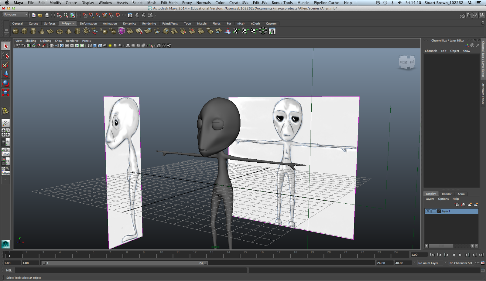
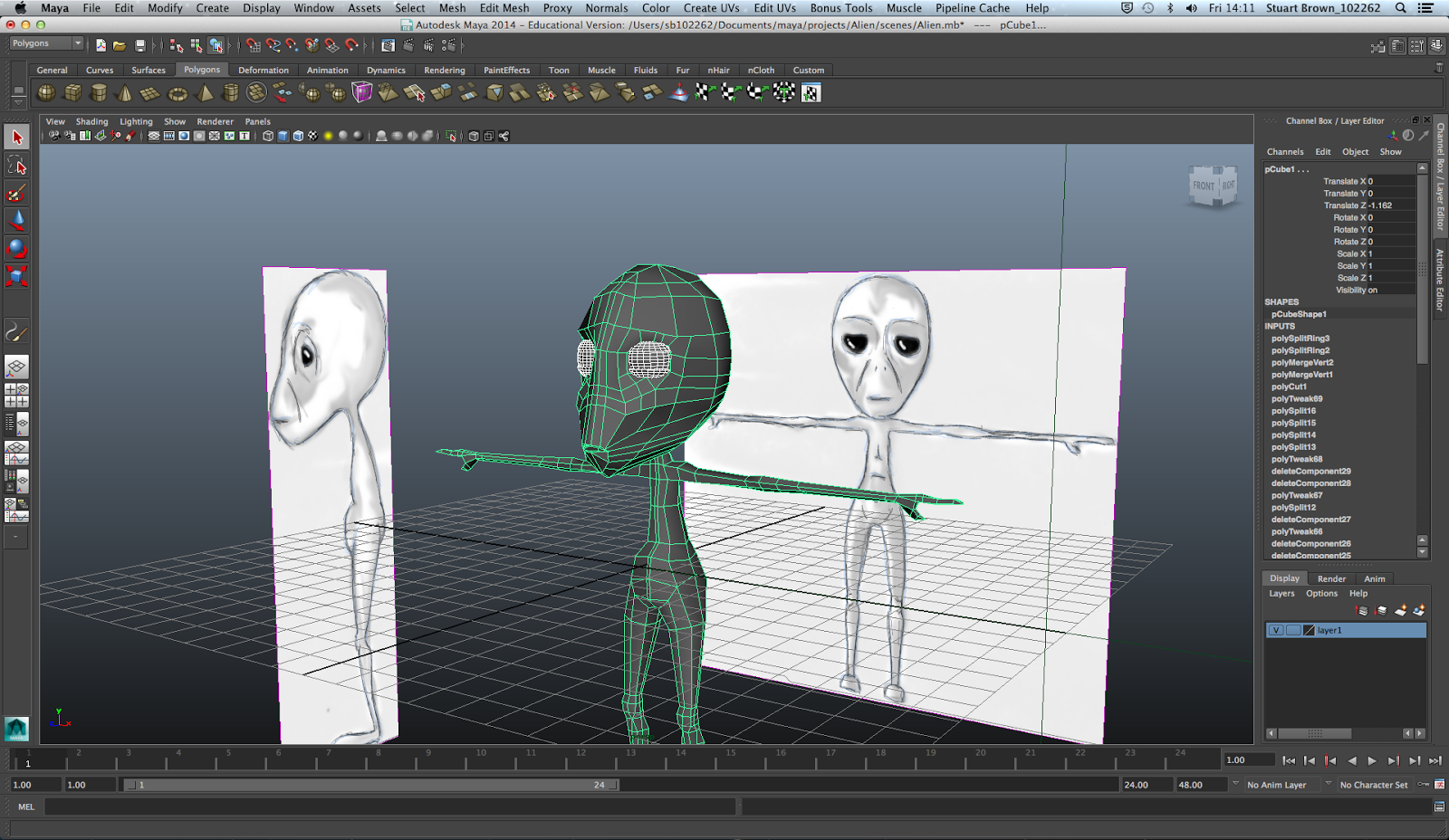
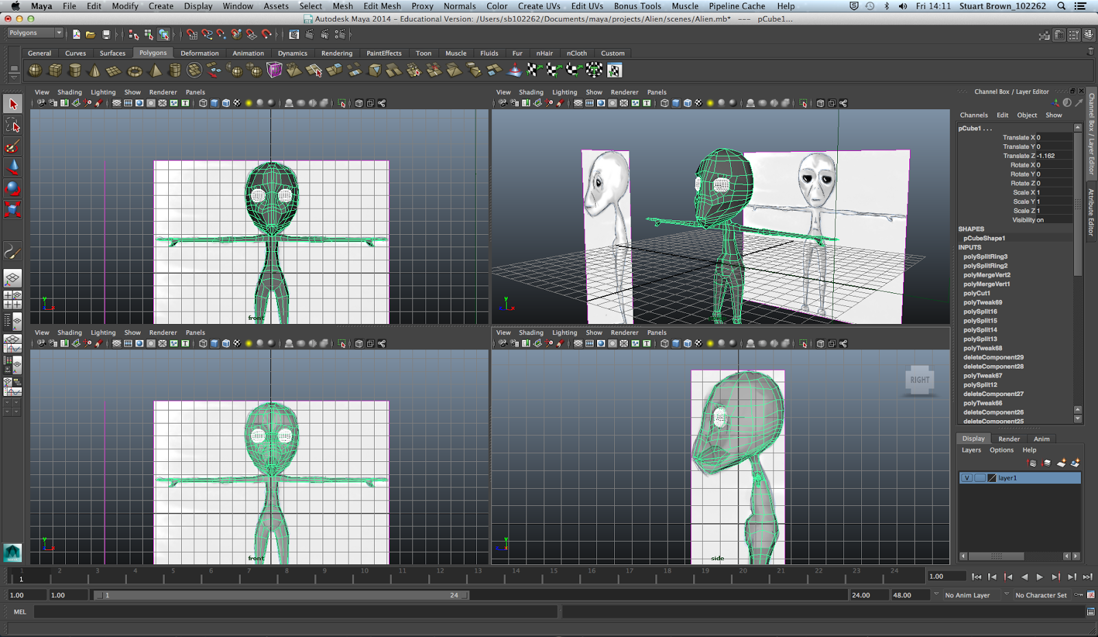
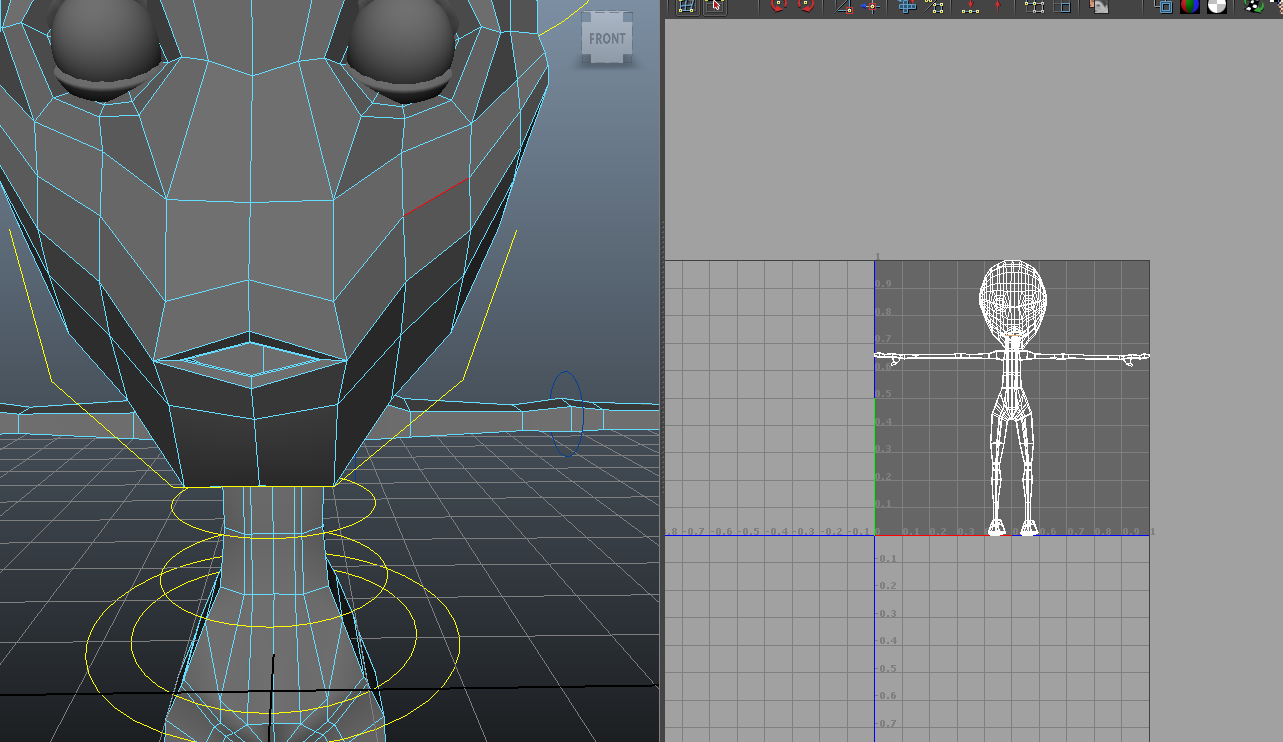
Starting from a cube and extruding the faces, and using the edge loop and interactive split tool I followed the guidelines of the turn-arounds for the character placed in Maya to make the outline of the Alien character. Doing this in the orthographic views of front and right allowed exact copies of the outline, similar to tracing. By pressing 4 on the keyboard I am able to see the wire frame of the character, so it the turnarounds can be seen behind, and 5 to see the shaded version of the character more accurate to how he will finally look. 3 allows you to view the character in smooth mode which would be how the character will eventually be rendered. I learnt alot in this session and how moving vertices and edges can give an accurate representation of a drawing. I also learnt how surprisingly easy this process is that initially I was baffled by the starting point and outcome, as I only had to create vertically half the character and mirror the image to get the whole image. I look forward to the next session about rigging.
Week 2
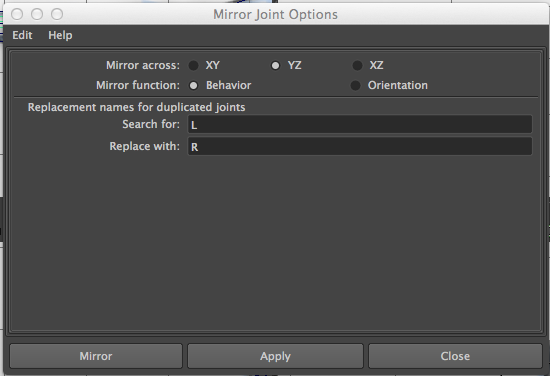
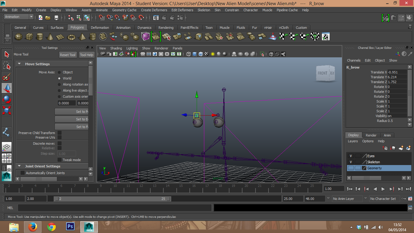
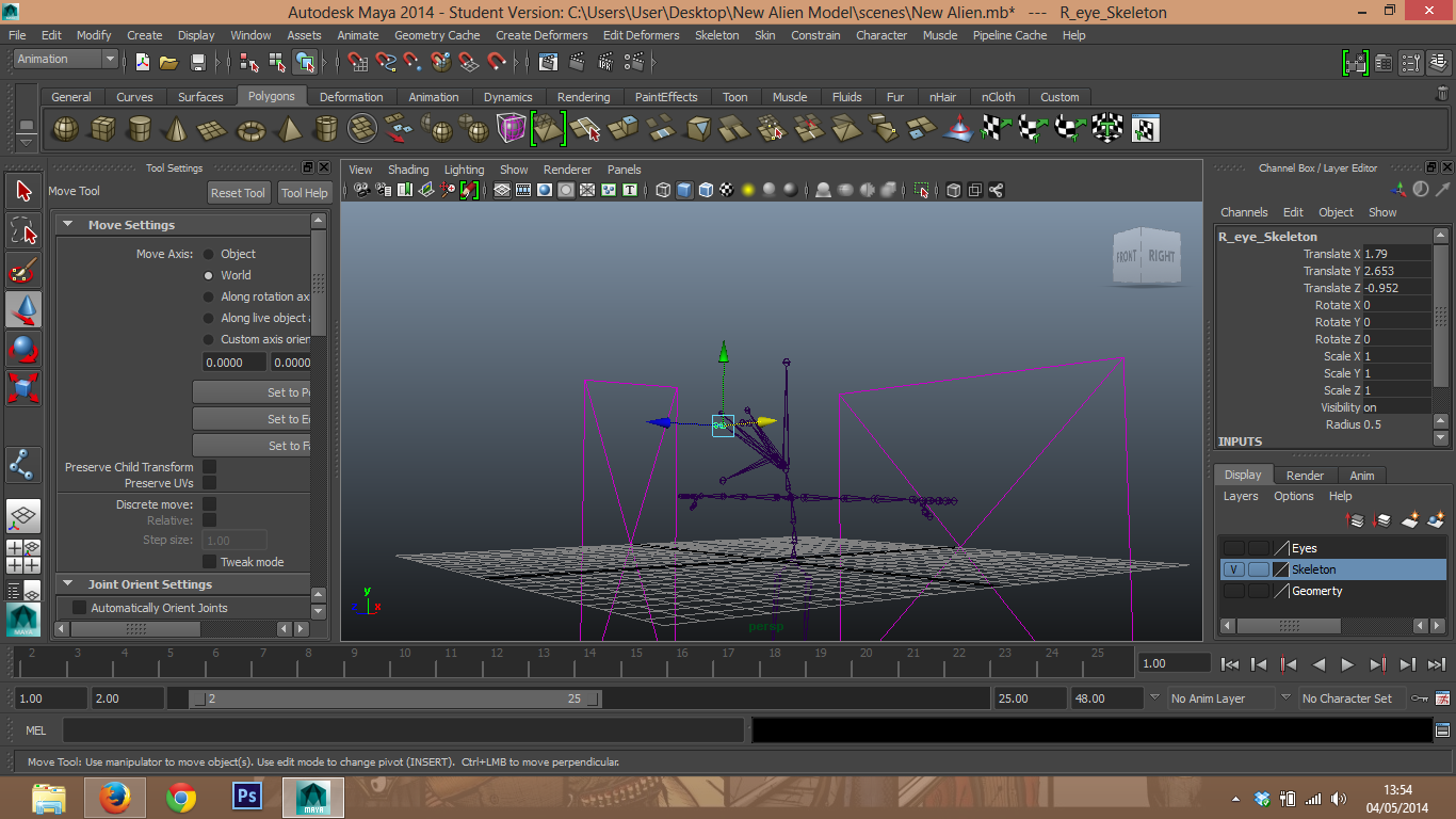
This session we will learn how the rig the character. Holding shift of the skeleton joint tool allows you to create a chain of joints, and if you wish to separately parent joints, click the child joint, and then holding shift and by clicking the parent joint Maya will connect these chains in a parent joint. Hold down D and moving a joint (whilst still in a straight line) will allow you to make amendments in the skeleton according to your model with no damage. When labeling these joints, if labeling them when for example creating the left arm, label them L_shoulder, L_elbow, L_wrist, ect, when mirroring the skeleton go to Skeleton, Mirror Joint, this box comes up...


Week 3
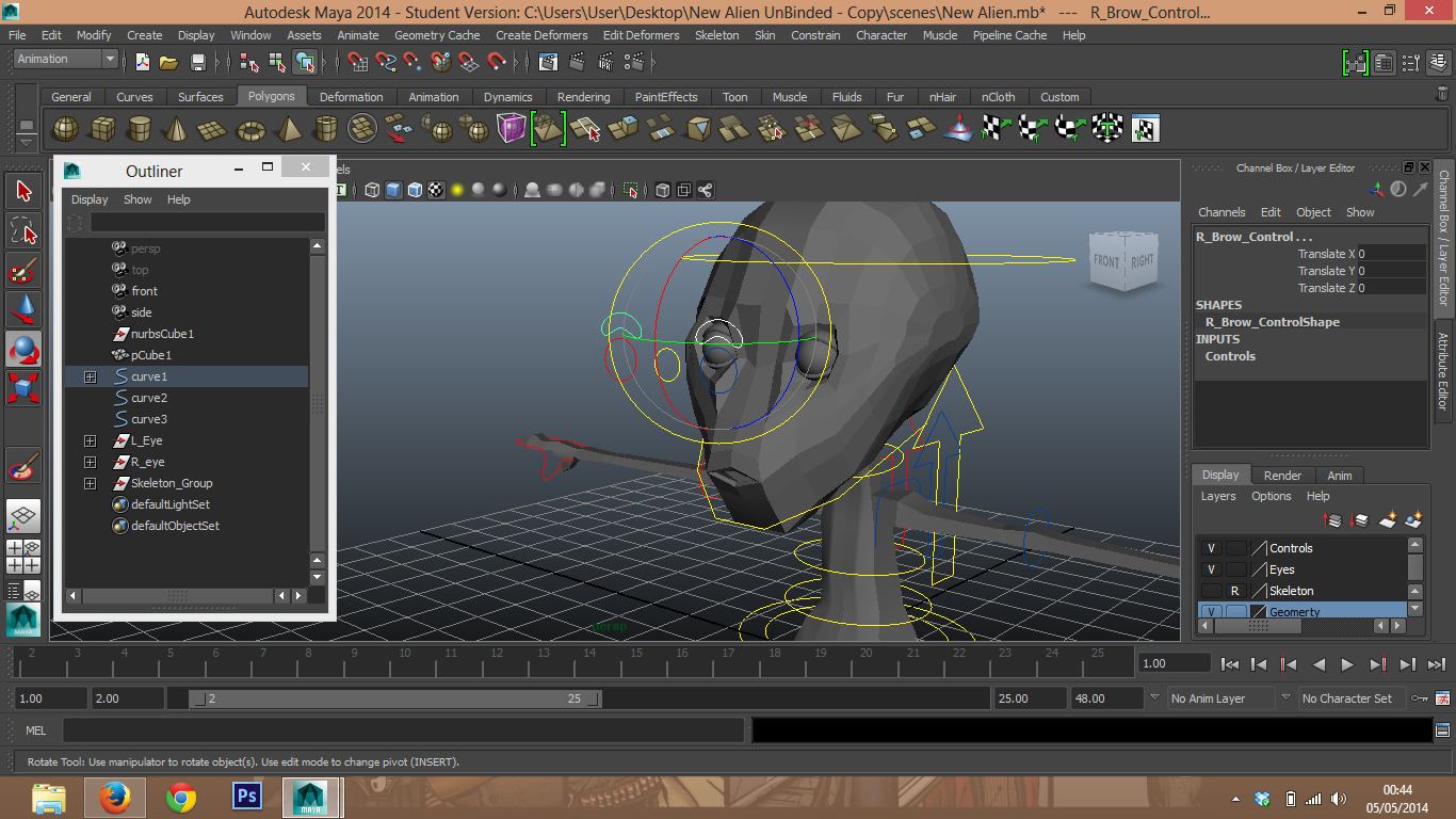
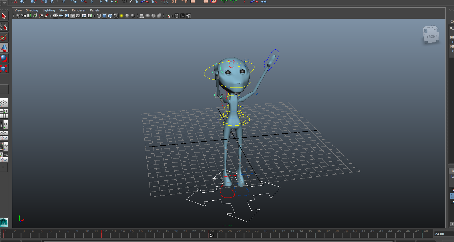
In this session we used NURBS primitives, CV curves, and text to create a control for the rig for the Alien character. by going to Create-NURBS primitives, and circle, I created the controls for elbows, spine, root, feet and head. to make this easier, I simply duplicated each joint, held V and middle mouse click to snap it to a different joint.


Week 4
Today I created a jaw bone with the CV curve tool, and colour coded the controls so it is clearer, the left side blue, right side red, and center yellow. I did this by going into the attribute editor, and looking into the drop down menu of Drawing - Drawings overrides, ticking enable overrides and changing the colour. I then moved the center of the controls to the appropriate part in the skeleton, presssing W, and holding D and V and middle mouse button moving it. I applied orient constraints to most of these controls, ticking the boxes maintain offset and constraint all axies, apart from the elbow as obviously elbow joints only move in one direction. I used aim constraint on the eyes so moving its control would alter the direction the eyes are looking, and a point constraint on the eyebrows. I then parented each joint to create a hierarchy so that if I moved for example the head, the eyes and jaw would move with it.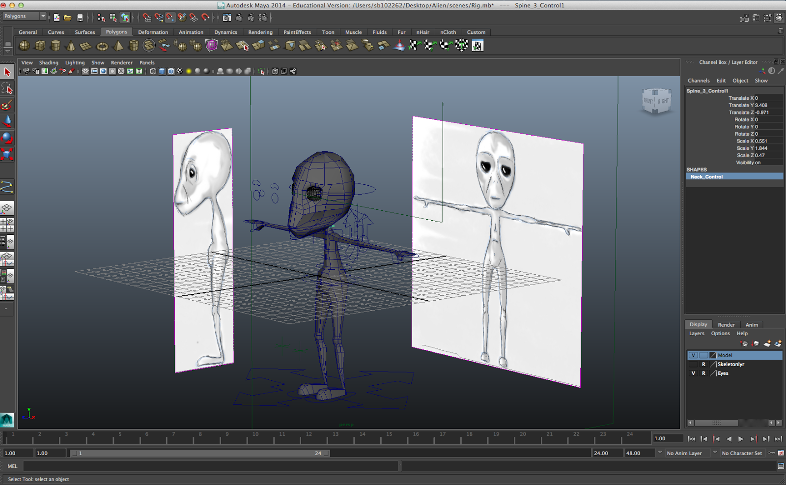

I dropped down the Skeleton menu, and pressed IK handle tool to bring up a new window. By using the Rotate Plane solver on the leg to ankle, and the Single Chain solver from the ankle to ball of foot, and the same for the ball of foot to toe. Slick the knee control, shift and click the ankle and go to the drop down constrain menu - Pole Vector, this allows the knee control to control the direction the knee is facing. I then simply parented all the skeleton from its highest hierarchy point to the master control on the floor, and the feet and knee controls too.


Week 5
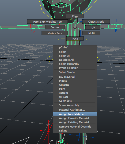
The next stage was binding the mesh to the skeleton using a smooth bind, found under the Skin drop down menu. I deleted my gemetry's history and froze its transformations ensuring they were all at 0. I right clicked the skeleton, selected select hierarchy and binded the mesh. I then painted the Aliens weights using the paint weights tool.
I selected the geomerty and double clicked the tool to bring up the tool settings, allowing me to chose the brush and between 'Replace' (which replaces the influence on the model from the skeleton) and 'Smooth' (which smooths out the harsh influence to the non existent and lesser influence). This process went fairly quickly and I moved swiftly on.


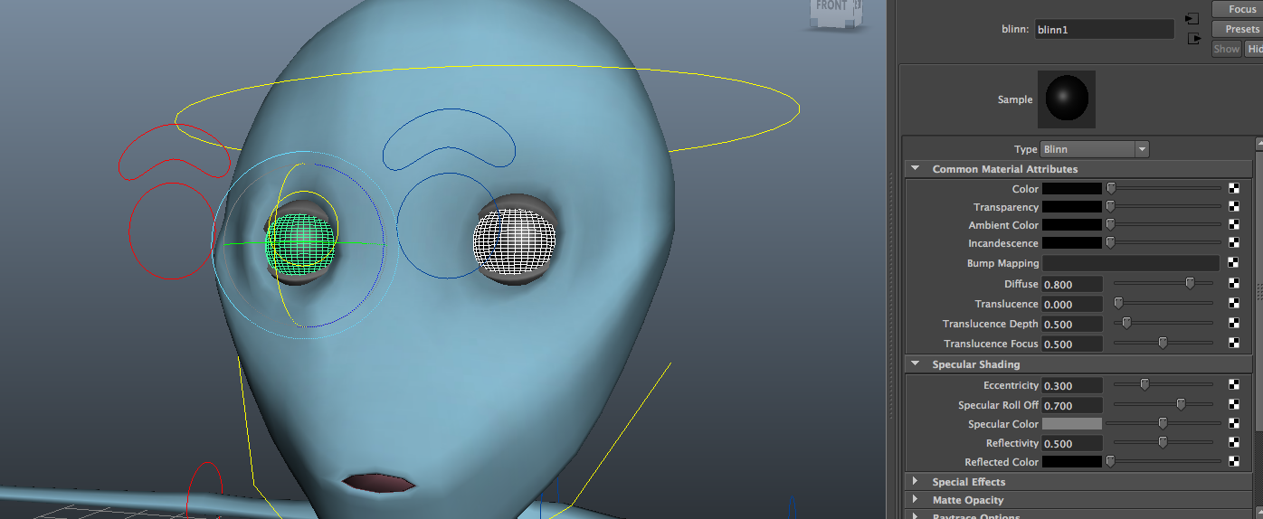
I then added attributes to my rig. Firstly, the eyes. I added an attribute to the eye controls by going to modify, Add attribute.


I then keyed the eyelids closed when the blink was at 10, and then set the blink to 0, rotated the eyelids to open at the state I wanted and pressed key again. This allows the eyes to blink when you pres the Blink attribute, and with the middle mouse button scroll side to side.
After trying to produce walk cycles, I found my Alien's paint weights weren't working, the influence I painted seemed to show while I did them but if I clicked on the next joint to paint influence, the paint I just applied vanishes. As this make the model unusable in Unity and un-animatable, and I could not find any solution to the problem I decided rather than waste time looking (after a hefty search) to start again immediately.
2nd Attempt
I continued to try by unbinding the geometry, deleting all history and freezing the transformations, but that also proved unsuccessful. I then spent my time re-modeling the Alien in a completely new scene to see if there was a problem with the mesh, I then copied and pasted the new folder to a new location so I had a back up, and binded one to the old skeleton and controls by importing them, but again the same problem occurred. I am unsure why this keeps happening, and has proved extremely stressful, and defining this Alien exercise as without doubt my least part of this project by far, and something I wish never to attempt again, but will have to try yet again.


3rd Attempt
Next I used the back up document of the new mesh, that I had not imported anything into or from, and started making a completely new skeleton. As I am now approaching the hand in date I have downloaded a student copy of Maya to my personal lap top and had to borrow a mouse from a friend to work on this. Though I have vigorously despised this process, I have learnt alot and this second time completing it has been far quicker and less troublesome than the first, as I have been able to apply what I learnt from the first attempt to speed this process up. Though it has been quicker I have still not identified anything I have done differently therefore my biggest worry is that I could simply finish with the same issue as the last.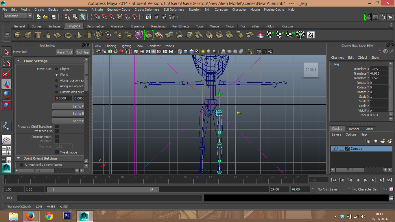
The next step is to re make a control system for the new Alien. Again this went quickly having already done the process, using NURBS Primiitives, CV Curbs in linear and cubic formats, and using the D and V buttons to move their rotational points. I finished by colour coding the controls the same way I had previously.


I then parented the controls in the correct hierarchy and applied orient constraints to most controls, other than the eyes which had aim constraints and eyebrows which had aim constraints.

I then placed Rotate-Plane Solver IK handles on each leg, and Single-Plane Solver IK going from the ankle to the ball of the foot, and another from the ball to toe. I then put pole vector constraints to the locators to control the position of the knees and parented them the the foot control.


After smooting the mesh, I frooze its transformations and deleted its history before binding the geometry using smooth bind and the settings: Selected joints, Closest first, Dual distance, Post, and with an maximum influence of 3 and a drop of rate of 4. But when I started to weights pianting, the same problem arose with random segments of veteces not applying the influence I was painting.


4th Attepmt
I then tried doing the bind without smooting the model as I thought perhaps the amount of veteces is causing a problem. It seems I was correct, as so far I have had no strange anomaly in any vertex. The wieght painting has been completed with no issus and has been double checked multiple time. I am very proud I have found the issue myself through trail and error despite my frustation and stree I have managed to fix the problem. It seems when I went to mesh>smooth mesh before binding Maya has created extra faces and vertex that have for some reason not complied with wieght painting in my models. But I will finish the model to the breifs requirments and then attempt to smooth mesh the piece for a more visually appealing appearence.

I then added the attributes like I had previously described also, by selecting the control points and going to Modify>Add Attribute and filling in the details accordingly as I have previously written.

For Peel heel I grouped the leg IK to itelf by highlighting it and pressing CTRL+G and re-named this Peel Heel group. For which I then moved its pivot to the ball joint. I did this for the other attributes and moved the pivot point to whereever it needed to be according to the particular attribute. I then used set driven keys to control the peel heel, and when the peel heel was at 0 I keyed it at its natural state, and moved it to rotate X 60 so it looked like the toe was coming of the ground, and again keyed it at this position.


I then did the same process for Toe Tap group, but placed them at negative 40 for the plus 10 and vise versa and keyed the attributes. I repeated this process with various suitable values for the other attributes including Toe Tap, Twist Toe and Twist Heel.


The next attribute I went on to use was the fist. I again used the same process but this time used multiple joints to get the hand to curve at the correct angle. I rotated all the finger joints from the knuckle to the finger end to get the exact look I wanted and then keyed it, repeating this for the thumb. As you can see as displayed will require some more wieght painting work to look more realistic.


I repeated the process for the blink exactly as I showed on the earlier model, and moved on to complete the forearm role, which would require the use of a mulitple divide node.
To make the wrist turn with the forearm joint also at a percentage, I went into the hypershade window (Window>Rendering Editors>Hypershade>Maya>Utilities>Multiply Divide.)


I then selected the components I would be using and placed them away from the others. I then pleced them in the following order for context that will become apparent; left wrist, Multiply divide node, left forearm. I middle mouse button pressed the left wrist, and dragged it into the multiply divie node, bringing up this window, for wihich I went to rotate X to input 1 as that is the value, and input 2 will be the multiplier, and the right wrist will go into input 1 Y:

Once they were highlightes blue they were applied, so I pressed on the forearm mulipy divide node and middle button dragged it on the left fore arm opening up a small window to which I chose the option 'Other' once again. The new window showed the inputs of the mulitply divide nodes and the outputs of the left fore arm. This is why placing them in this order at the begining makes sense. The input X that we plugged the left wrist into, so the output of X, we now plug into the rotate X of the forearm role.

Once this is done I repeated the same process for the right wrist, which is made easier as it is already connected to the multiply divide node, only using it for input 1 Y as I said ealier, this will be clear as input 1 X will be unusable now. I then went into the attribute editor of the Multiply Divide and entered 0.5 to bot left and right so the fore arm moves at half the rotation of the wrist.

I then went into paint wieghting to clear up some outstanding issues that could be seen not the atributes had values and moved on to scale and smooth the model, something I now know must be done after binding the model.

To do this I went to Mesh under the polygon display and pressed smooth. Previously I had been to told to smooth a model it must be done before binidng it to its rig, which is why I have had so many problems with this model, never the less I have found a solution and hopefully the rest of the process will go smoothly.


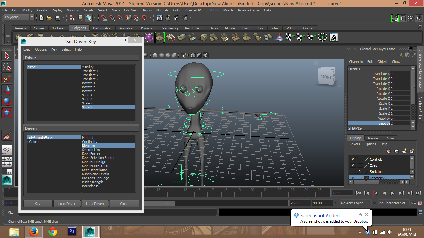
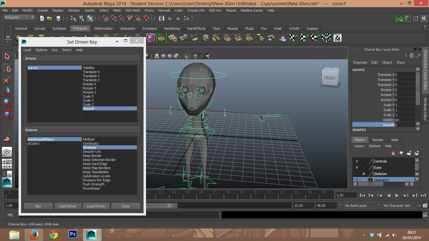
Divisons = 1 is high poly (like he origonally looked) 2= how I chose him to look as 3 seems too much. I then added an attribute to the master control called smooth. I then key framed this so I could control the smoothness of my model through set driven keys.


I then selected the skeleton root as a group and the gemoetry and used a scale constraint so that I could alter the size of the model. I then completed some 'house keeping' essenisally turning the visability of the IK handels off, and lock and hiding and rotational and translate options where uneccassary (such as the elbows that only need to rotate in Y) by highlighting them, right clicking and selecting lock and hide. I then made a quick select set by selecting each joint in the hierarchy from the ends to the root, and finally the master control and going to Create>Sets>Quick Select Set and adding to my custom shelf, as this will make animating far easier.
I recently found out that the reason I smoothed the geometry before binding it was because if I didn't Unity wouldn't read the smooth. I was very annoyed at this as I thought after all my hard work I was rewarded by finding my own solution to the problem but in actual fact had made another. This did make me feel like giving up, but I persevered as I no longer had time to try to do the model again.
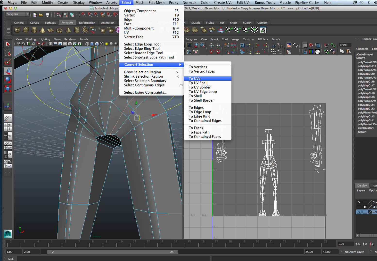
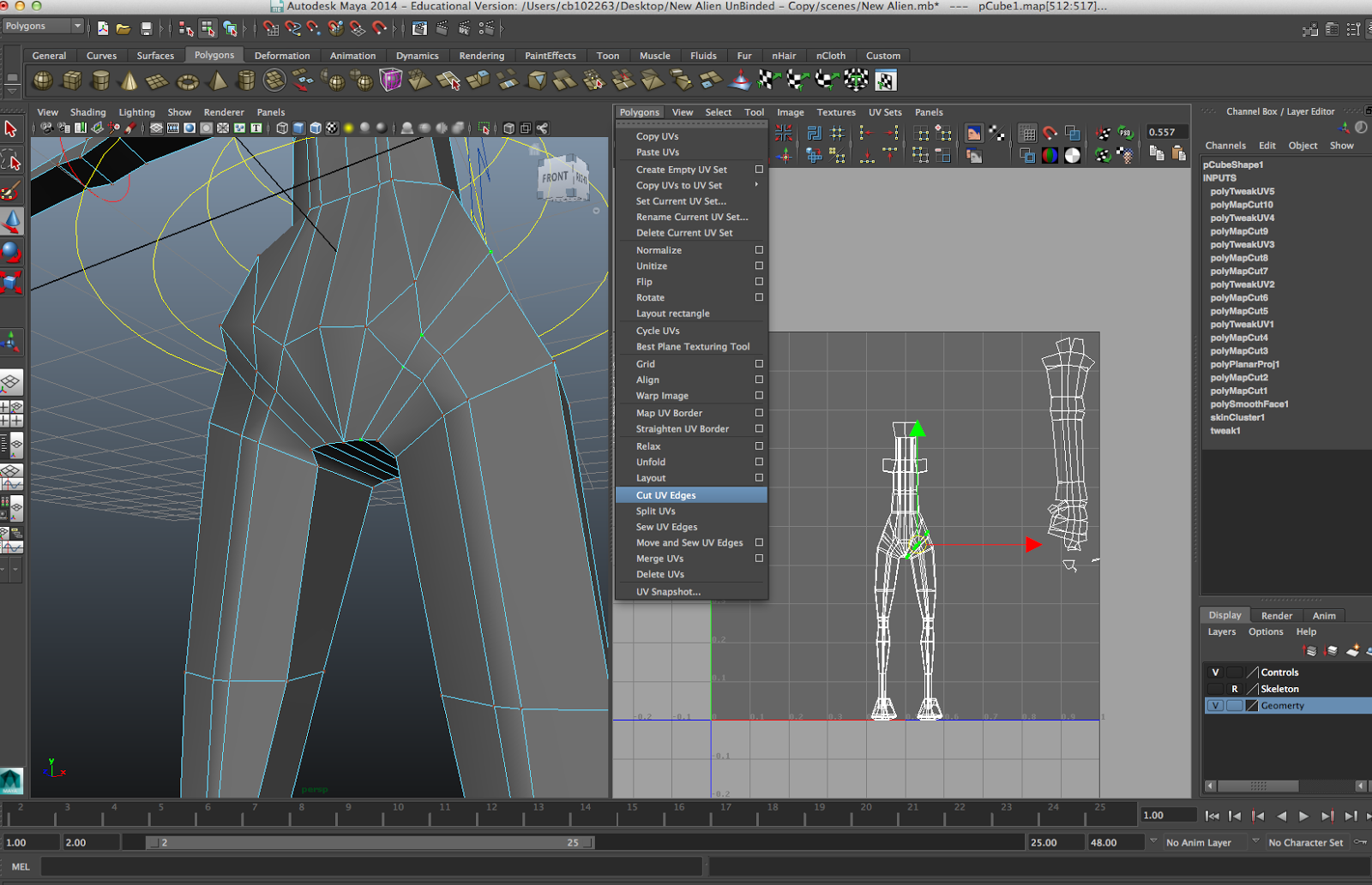
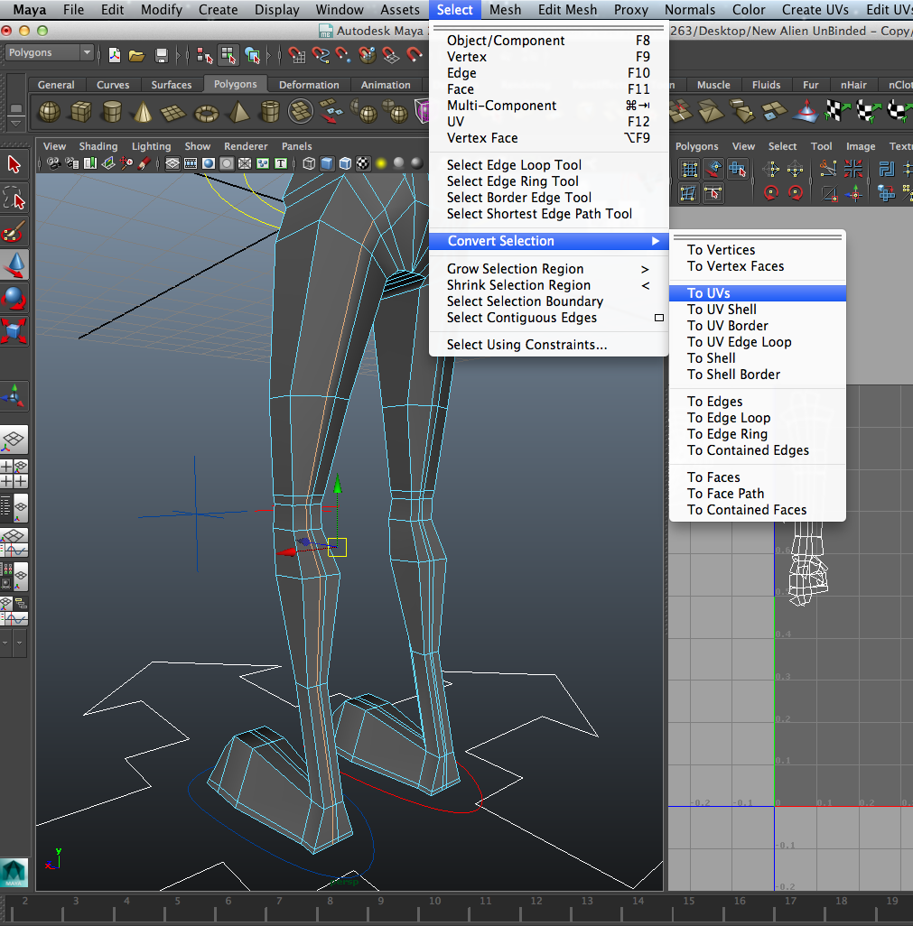
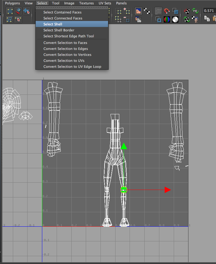
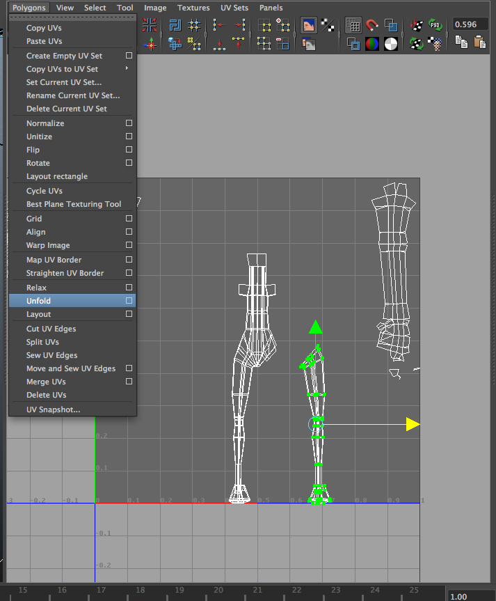
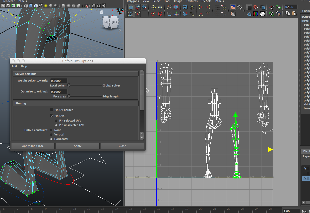
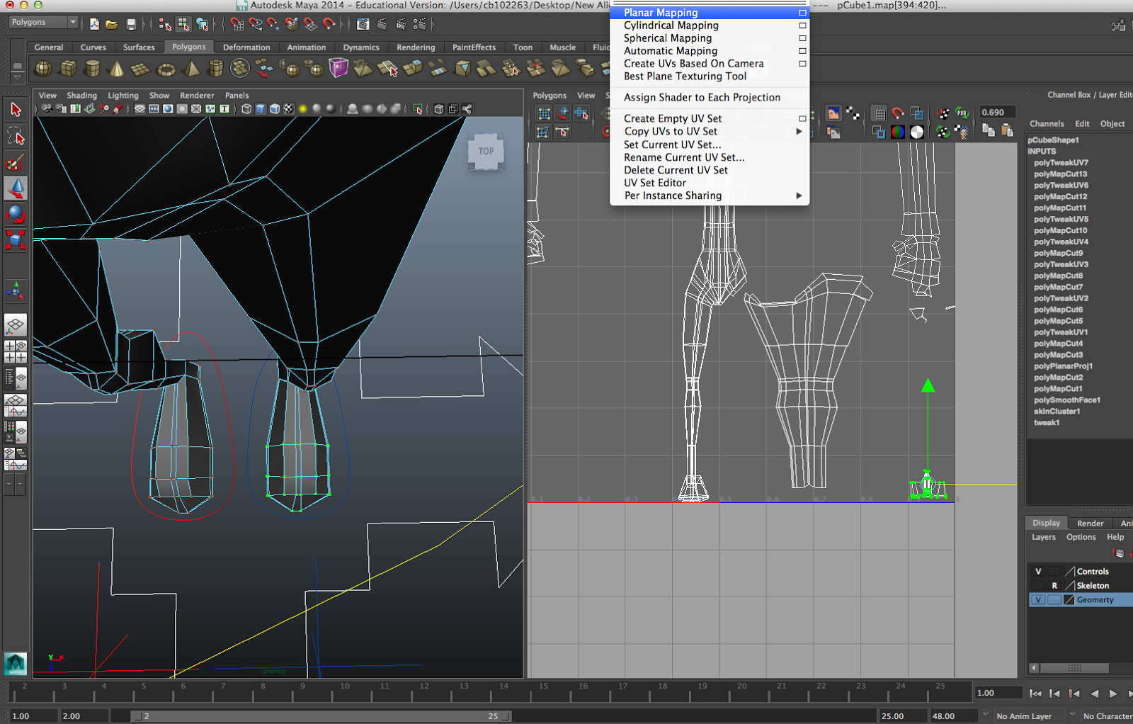
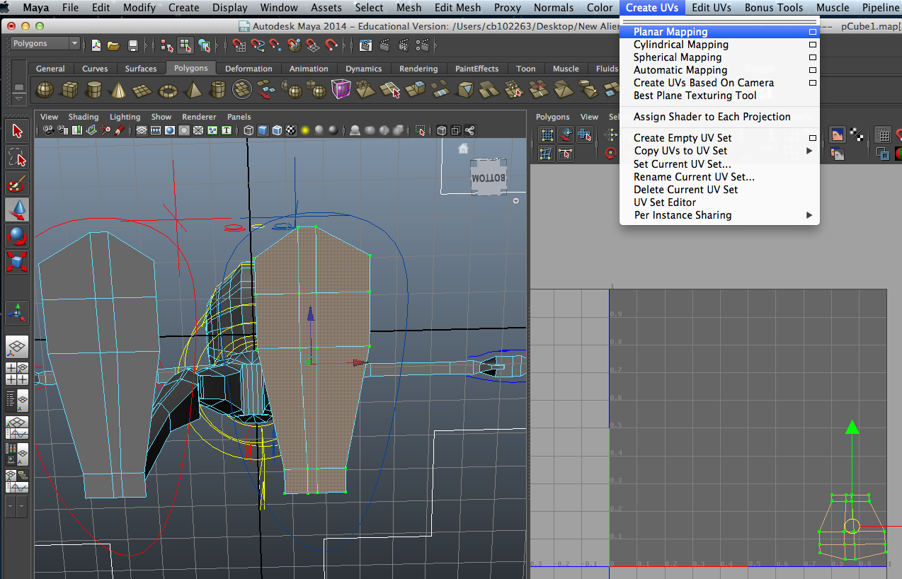
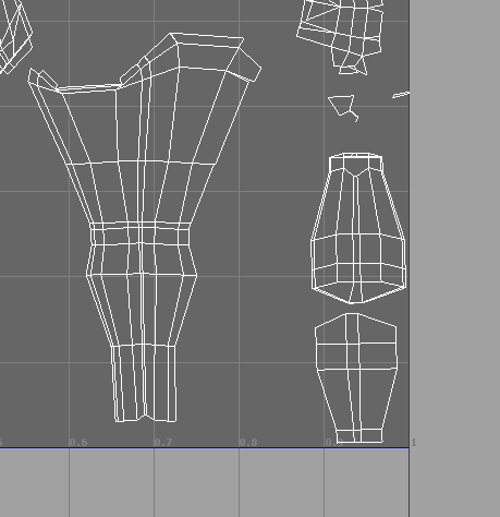
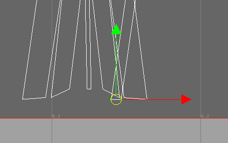
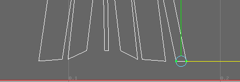
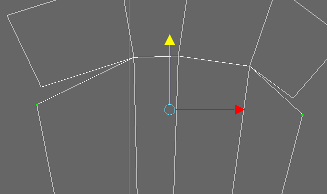
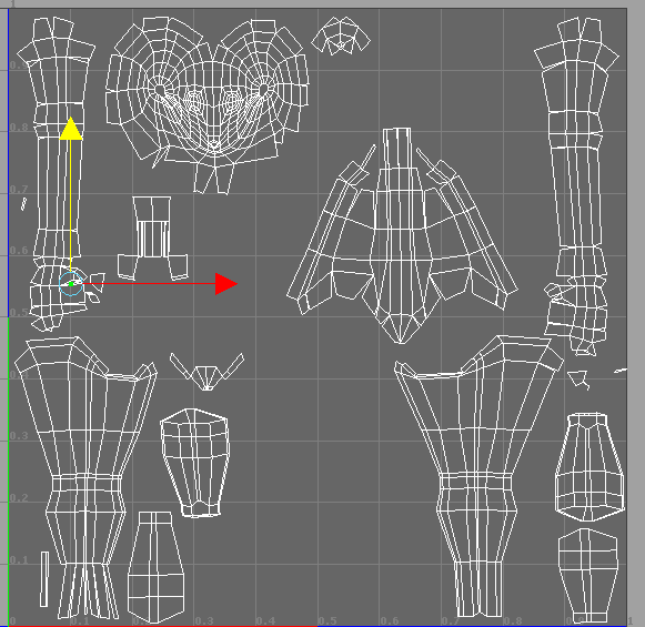
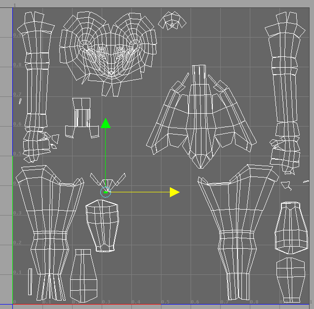
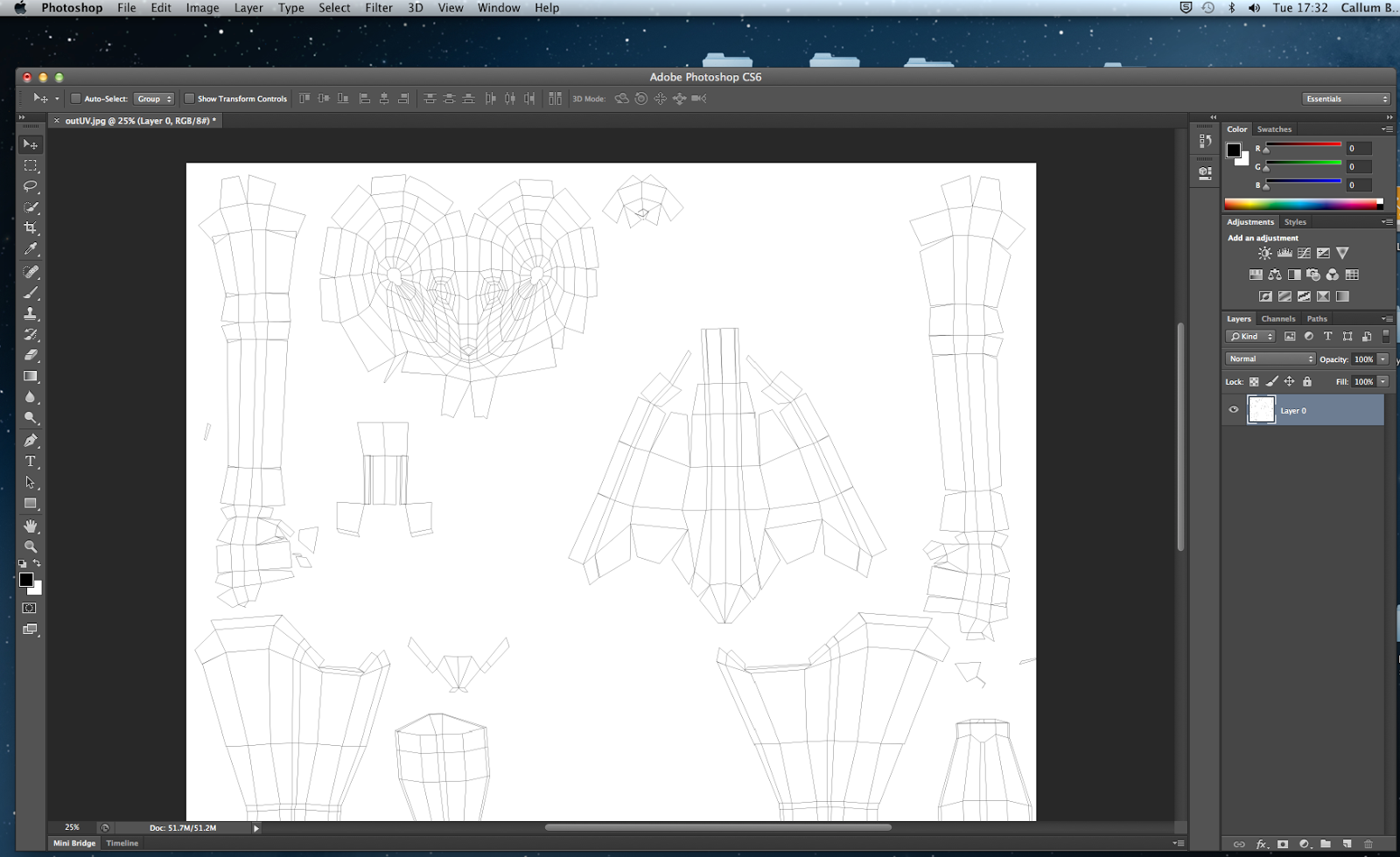
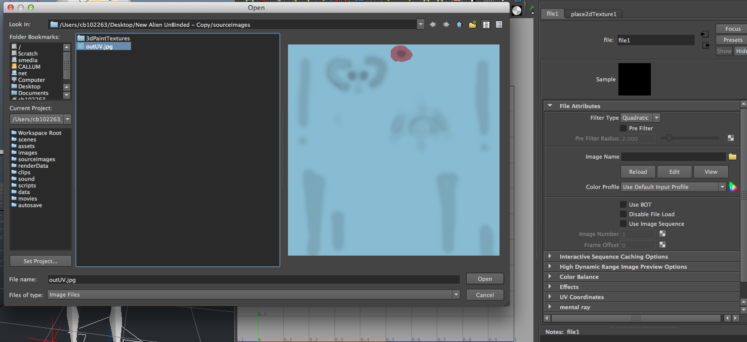
I quickly UV mapped my Alien using Planar Mapping and the UV selection after right clicking to move UV's not vertex's. By selecting an edge and pressing Polygons> Sew UV Edges I could re connect any edges that had become unbound. I unfolded geometry by selecting the edges and pressing convert selection to UV's going to cut UV edges. I then clicked on a UV and pressed Select>Shell and moved it away from the UV's, and then went to the Polygon menu and Unfold which usually worked perfectly when the shape is similar to a cylinder, but when no it could be unfolded manually with the UV selection. I didn't find any issues in the UV process as I have completed it a number of times, and has been my favourite part of Maya projects in the past (usually because it takes place mainly in Photoshop and not Maya!) I have left Screen grabs below of the process as I am running close to the deadline and have little time to explain this somewhat straight forward process, but I have displayed screengrabs below.


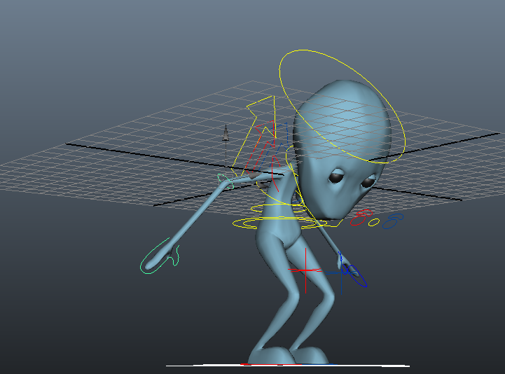
I then animated my Alien to perform a Jump, Idle and Walk cycle using key frames. I would select a part of the Alien and press on the quick select set and press S. This was fairly straight forward and provided good practice for the animation we will have to complete.
After trying multiple times to import this to Unity for an unknown reason the Alien seems not to work. I believe this may have something to do with the outliner order and the grouping of my Alien, which is making it awkward for unity to understand. But now that the deadline is so close I simply do not have the time to go back and complete this alien for a 5th attempt. I do believe I have displayed every stage necessary of this process and will now provide a character turn table in Unity to prove I can do this process also. I am very annoyed that this alien has proven so troublesome and that even after a 5th attempt I still cannot get it to work, which makes me disappointing in myself as I hoped to overcome my problems in time, but unfortunately there has been so many and I have had to go back and start from scratch which has resulted in huge amounts of stress and loss of time and now I have finally ran out. I regret not being able to display his finished animations in unity but hopefully displaying my ability to continue this process with a different character will substitute enough, along with the Aliens animations in video.
Here is a video of my Aliens animations: https://www.youtube.com/watch?v=cdoGKMRx4Dw&feature=youtu.be
I used the Raccoon character to display my turn arounds as the Platypus was having to be remade also and is currently just unavailable at this time. As you can see the Raccoon character has imported fine and works beautifully, so why my Alien hasn't worked I do not know. This process has proved very stressful and difficult but I am glad to have come out of the other side of it with better understanding of the process but in all honesty I would avoid using Maya again. I look forward to moving on to animating the actual film as the keyframing and animating stage of this has been far less difficult and very straight foraward and I do not mind continuing this work. I also enjoyed the texturing stage but the work actually modelling the charcter and rigging it is something I do not whish to repeat, and would seek to work with someone who enjoys this stage in the future.
Here is the Raccoon Character Turn table in Unity: http://youtu.be/e25hxxh8VxI
No comments:
Post a Comment